Introduction
In this article, we present the various components used to separate the oil from the refrigerant and reintegrate it into the compressor crankcase(s).
If you’d like more information on oil reintegration methods, click here.
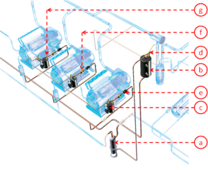
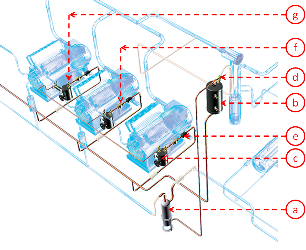
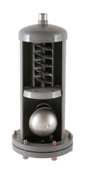
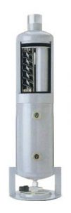
A : Oil separator – TURBOIL / F / R
The oil separator is located on the discharge side of the refrigerant compressor(s):
It separates the oil contained in the refrigerant.
The oil recovered in the separator is stored in the lower part containing the float/valve/needle mechanism.
When the oil level is high enough to lift the float mechanism, the valve/needle system opens, allowing the oil to flow back into the compressor crankcase(s).
The oil returns naturally, thanks to the pressure difference between the oil separator (HP at discharge) and the crankcase(s) (BP at suction).
Hermetic separators
The TURBOIL, designed for single-compressor or low-capacity refrigeration systems.
Removable separators
TURBOIL-F hermetic or semi-hermetic separators are designed for all types of installation, and are particularly suitable for multi-compressor refrigeration plants. The removable part concerns the float/valve/needle mechanism, which is the most fragile part, as it is subjected to vibrations and impurities. The float can be damaged by vibrations, and the needle can be clogged by impurities.
Tank oil separator
The TURBOIL-R, these products integrate the oil reservoir function and have no float/valve/plug mechanism. Oil return is therefore high pressure, requiring the use of either a pressure reducer or an electronic oil level regulator.
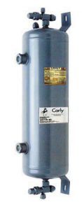
B: The oil receiver – HCYR
Complex refrigeration systems require systems for varying refrigeration output (speed variation, compressor cascades).
Siphons and oil traps can be created in the refrigeration circuit, trapping the oil present in the refrigerant.
The oil receiver ensures that the compressors are supplied with oil during the start-up phase and when the system is running at reduced output.
The volume of the oil receiver is determined by the number of compressors placed in parallel and their swept volumes.
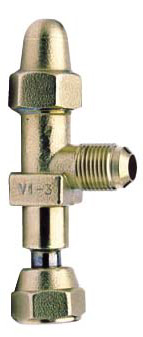
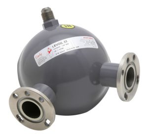
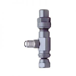
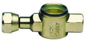
C: LEVOIL mechanical oil level regulator
The oil level regulator is installed in place of the sight glass on the refrigeration compressor, and enables :
- visualize the oil level in the compressor crankcase
- maintain oil level in accordance with compressor manufacturer’s specifications.
The oil level regulator features a float/valve/needle system that ensures oil supply to the crankcase as soon as the oil level falls below the nominal level (usually in the middle of the compressor oil level sight glass).
Oil level stability in the compressor crankcase is achieved by maintaining a constant pressure difference between the regulator oil supply and the compressor crankcase pressure.
The pressure difference must be compatible with the operation of the level regulator, e.g. between 1bar and 4.5 bar for the LEVOIL range.
If the oil sight glass attachment on the compressor crankcase does not match the standard flange type of the oil level regulator, adapters (HCYN 1A) can be used (see page 51.6 of the technical catalog).
LEVOIL regulators come in 3 main families:
- LEVOIL 22 and LEVOIL 23, universal controllers
- LEVOIL 23 BO and 23 SC, specific controllers
- LEVOIL 33 RE, universal adjustable controllers
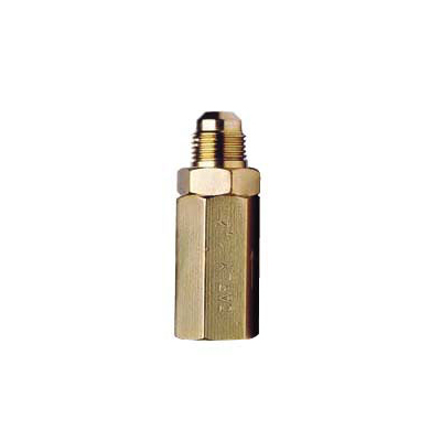
D : The tared valve – HCYCT / HCYCTR
The tared valve maintains excess pressure in the oil reservoir to ensure the correct oil supply to the oil level regulators.
It is mounted on the oil tank and usually connected to the refrigeration machine’s suction pipework.
The valve setting relieves excess pressure from the oil receiver to the suction manifold, and maintains a constant pressure difference between the oil supply pressure to the oil level regulators and the compressor crankcase pressures.
The valve setting can be set at the factory (HCYCT 1 = 0.35bar, HCYCT 3 = 1.4bar and HCYCT 4 = 3.5bar) or adjusted on site (HCYCTR: 0.35 bar < P < 3.5 bar).
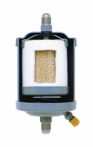
E: Oil filter – HYDROIL – HCYBF – HCYF
The oil filter retains impurities contained in the oil, previously separated and stored, before reintegrating it into the compressor(s) crankcase.
The oil filter may contain a metal screen (HCYF), a synthetic fiber filter combined with a desiccant (HYDROIL 163) or a replaceable fiber cartridge (HCYBF).
HYDROIL 163 is particularly recommended for use with HFC-type fluids combined with highly hygroscopic POE oils.
The addition of desiccants (molecular sieves) adsorbs the moisture contained in the oil before reintegrating it into the compressor crankcase, and delays or eliminates the formation of acids.
The use of an oil filter is particularly recommended when using oil level regulators.
The oil filter is usually placed between the oil separator and the compressor, or between the oil receiver and the oil level regulator.
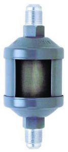
F: Oil sight glass – HCYVP
The oil sight glass indicates the presence and color of oil.
It can be placed either on the oil separator return line, to check that the oil separator is operating correctly, or on the oil level regulator supply line, to check for the presence of oil.
G : Isolation valve – HCYVI
The isolation valve is designed for mechanical oil level regulators.
It enables the regulator to be isolated for cleaning or replacement without having to drain the entire oil circuit.